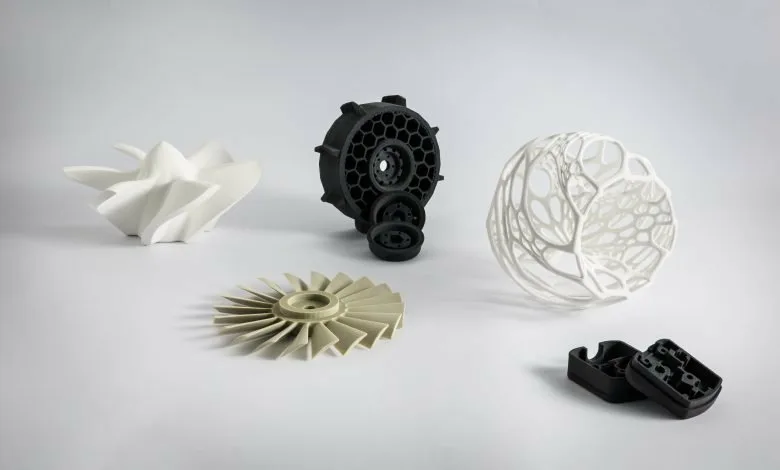
Selective Laser Sintering (SLS) 3D printing has transformed manufacturing, providing extensive capabilities for creating complex geometries, functional prototypes, and high-performance end-use parts. However, like any advanced technology, it has its challenges. This guide aims to help users overcome common obstacles in SLS printing, covering material selection, design principles, troubleshooting, and cost-saving strategies.
Understanding the Basics of SLS 3D Printing
How Does SLS 3D Printing Work?
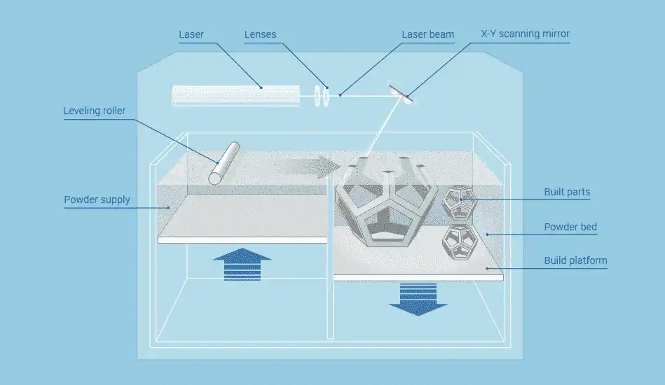
SLS is a powder bed fusion technology. The process involves spreading a thin layer of polymer powder on the build platform. A high-powered laser then scans the part’s cross-section, heating the powder to its sintering point and fusing it. The build platform lowers, and a new powder layer is added. This repeats until the part is complete. After printing, the parts are cooled, and excess powder is removed. The unused powder acts as a natural support, enabling complex designs without additional supports.
What Materials Are Used in SLS?
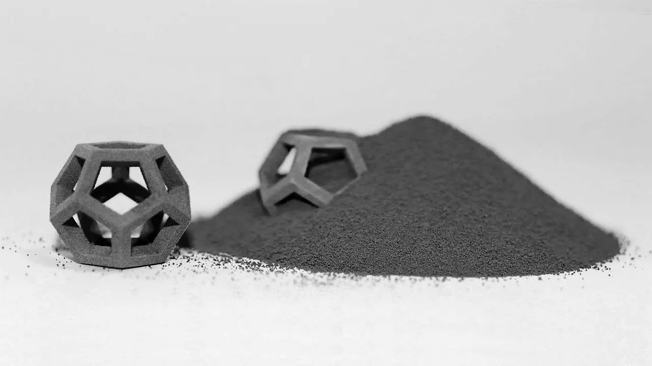
SLS mainly uses thermoplastic powders. Commonly used materials include PA12 (Nylon 12), PA11, TPU, and composites. PA12 is durable and lightweight, suitable for prototypes and functional parts. PA11 has high ductility and is used in medical devices and automotive parts. TPU is flexible and wear-resistant, applied in footwear and seals. Composites, with fibers like carbon or glass, offer enhanced strength for aerospace and structural components. Material selection should be based on project requirements such as flexibility, strength, or heat resistance.
Advantages of SLS Printing

SLS offers several benefits compared to other 3D printing methods like FDM or SLA. It doesn’t require support structures, saving design and post-processing time. Printed parts are mechanically strong and isotropic. SLS allows for intricate internal channels, thin walls, and lattice structures, providing great design freedom. It also enables batch production by stacking and nesting parts in the build chamber, maximizing productivity and minimizing waste. These advantages make SLS ideal for functional prototypes, end-use parts, and short production runs.
Common Applications of SLS 3D Printing
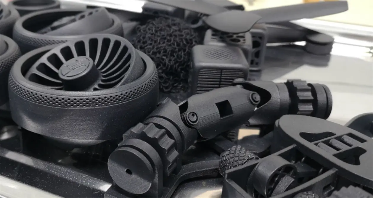
SLS has diverse applications across industries. In aerospace and automotive, it produces lightweight and strong components and prototypes. In the medical field, it’s used for customized implants, prosthetics, and surgical guides. For consumer goods, it creates custom eyewear frames and durable footwear soles. In industrial tooling, it manufactures jigs, fixtures, and functional machine parts.
How Does SLS Compare to Other 3D Printing Methods?
| Feature | SLS | FDM | SLA |
| Support Structures | Not required | Required | Required |
| Material Strength | High (isotropic) | Moderate (anisotropic) | High (brittle in some cases) |
| Surface Finish | Rough, needs post-processing | Layer lines visible | Smooth, detailed |
| Cost | High initial investment | Low to moderate | Moderate |
| Applications | Functional parts, prototypes | Prototypes, hobbyist projects | High-detail models, prototypes |
While SLS has a higher initial cost, its ability to produce strong, support-free parts is advantageous for professional applications.
Common Challenges in SLS 3D Printing
1. Material Challenges
1.1 Powder Degradation
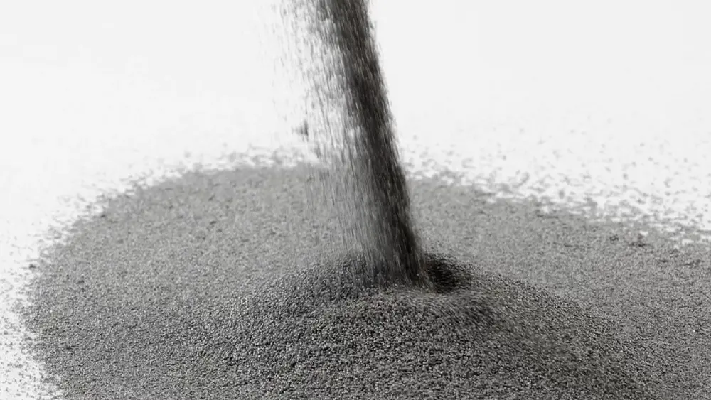
The sintering process exposes SLS powders to high heat, which can degrade their quality over time. Degraded powder leads to inconsistent melting, resulting in brittle or weak parts. To address this, a mixture of virgin and recycled powder (e.g., 30% virgin and 70% recycled) can be used to maintain quality while reducing costs. Regular monitoring of powder condition and replacement when necessary is also essential.
1.2 Limited Material Options
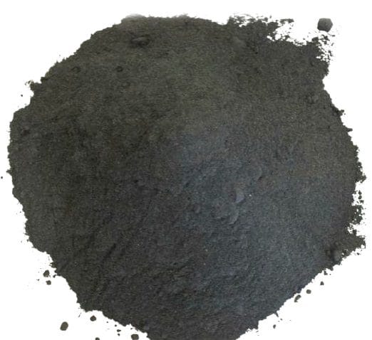
Although SLS materials like PA12 and TPU are versatile, the range is narrower than other 3D printing technologies. Limited material choices can restrict applications, especially in industries requiring unique properties. Exploring composite materials or seeking specialized powder suppliers can help overcome this challenge.
1.3 Material Shrinkage and Warping
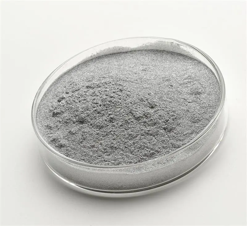
During cooling, SLS materials may shrink or warp, causing dimensional inaccuracies. To minimize this, proper design techniques such as maintaining uniform wall thickness should be employed. Ensuring the printer’s temperature calibration for consistency is also crucial.
2. Design Challenges
2.1 Wall Thickness
Thin walls can crack, while thick walls may cause internal stresses during cooling. Following recommended wall thickness guidelines for the material (e.g., 1 mm minimum for PA12) and using simulation software to validate the design can prevent these issues.
2.2 Overhangs and Unsupported Features
Although SLS doesn’t need support structures, overhangs or sharp angles can still cause problems. Powder may not provide sufficient support, leading to sagging or rough finishes. Avoiding steep overhangs (>45°) and using self-supporting angles, along with proper part orientation, can improve the print quality.
2.3 Internal Cavities and Voids
Parts with enclosed cavities can trap unsintered powder, complicating post-processing and potentially weakening the part. Adding escape holes with a diameter of at least 2-3 mm allows the trapped powder to flow out during depowdering.
3. Process Challenges
3.1 Laser Calibration
Precise calibration of the laser in an SLS printer is necessary for consistent sintering. Miscalibration can result in under-sintered or over-sintered parts. Regularly checking and calibrating the laser settings according to the printer’s manual, ensuring even scanning speeds and consistent energy distribution, is required.
3.2 Heat Distribution
Uneven heating in the build chamber can cause defects like warping or inconsistent density. Maintaining a uniform temperature in the build chamber and using printers with advanced thermal management systems can solve this problem.
3.3 Porosity and Density Control
Uncontrolled porosity can weaken parts or affect their surface finish. Fine-tuning parameters like laser power, scanning speed, and layer thickness to control density and performing test prints to find the optimal balance is necessary.
4. Post-Processing Challenges
4.1 Depowdering
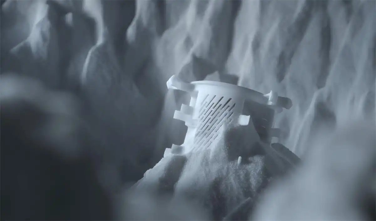
Removing excess powder can be time-consuming and difficult, especially for complex parts with internal cavities. Using compressed air or ultrasonic cleaning systems and automating depowdering for large batches can improve the efficiency.
4.2 Surface Finish
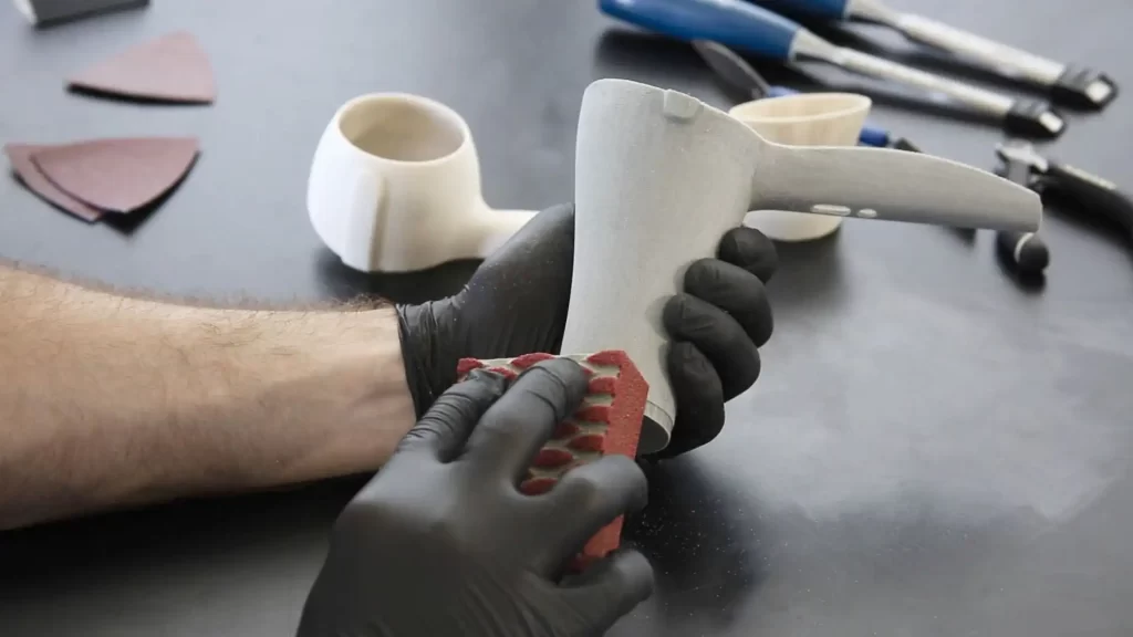
SLS parts often have a rough texture that requires additional smoothing. Post-processing methods like bead blasting, sanding, or chemical smoothing (e.g., vapor polishing) can enhance the surface quality.
4.3 Coloring and Coating
Dyeing or painting SLS parts can be challenging due to their porous nature. Using specialized dyeing solutions or coatings that penetrate the surface evenly can achieve better results.
5. Cost Challenges
5.1 High Machine Costs
SLS printers are more expensive than FDM or SLA machines. This high initial investment may deter small businesses or hobbyists. Considering entry-level SLS machines or outsourcing small projects to service bureaus can be alternative solutions.
5.2 Powder Waste
Although unused powder can be recycled, degradation reduces its usability over time. Implementing a powder reuse strategy (e.g., mixing new and used powder) and tracking powder performance can optimize usage and reduce costs.
5.3 Post-Processing Costs
Manual post-processing can be labor-intensive and costly for large batches. Automating post-processing steps wherever possible (e.g., using automated depowdering stations) can increase efficiency and reduce costs.
Tips for Overcoming SLS 3D Printing Challenges
1. Improving Material Quality
1.1 Use High-Quality Powders
The quality of SLS powders affects print resolution and mechanical strength. Source powders from reputable suppliers and look for certifications and material data sheets ensuring consistent particle size, flowability, and thermal properties. For high-precision parts, use fresh, virgin powder and limit the ratio of recycled powder.
1.2 Store and Handle Powder Properly
Powder is sensitive to moisture and contamination. Store it in airtight containers with desiccants and consider using a humidity-controlled storage system or drying oven before use.
1.3 Optimize Powder Reuse
Mix recycled powder with virgin powder at an appropriate ratio (e.g., 30% virgin, 70% recycled) and regularly monitor the performance of the mixed powder to reduce costs while maintaining quality.
2. Enhancing Design for SLS
2.1 Follow Design for Additive Manufacturing (DfAM) Principles
Designing for SLS requires following specific guidelines. Maintain uniform wall thickness (e.g., at least 1 mm for most materials), avoid sharp corners by using fillets, and include escape holes (at least 2-3 mm in diameter) for internal cavities to facilitate powder removal.
2.2 Optimize Part Orientation
Proper part orientation in the build chamber affects dimensional accuracy and surface finish. Orient critical surfaces upward for better resolution and position parts to minimize overhangs and thermal stresses. Software tools like Autodesk Netfabb or Materialise Magics can assist in determining the optimal orientation.
2.3 Incorporate Lattice Structures
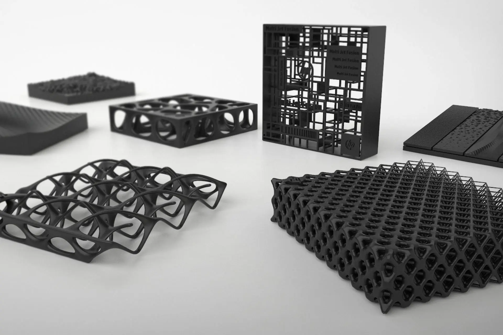
Lattice structures can reduce weight without sacrificing strength and are suitable for SLS. Use them in areas where strength requirements are lower to save material and costs.
3. Optimizing the SLS Printing Process
3.1 Fine-Tune Print Parameters
Each material and machine requires specific settings for optimal results. Key parameters include laser power, scanning speed, and layer thickness. Run test prints to find the ideal settings and document them for future use.
3.2 Maintain Thermal Consistency
Uneven heating can cause warping or weak points in parts. Ensure the build chamber maintains a uniform temperature and use printers with advanced thermal management systems. Regularly clean heating elements and calibrate temperature sensors.
3.3 Regularly Inspect and Maintain the Machine
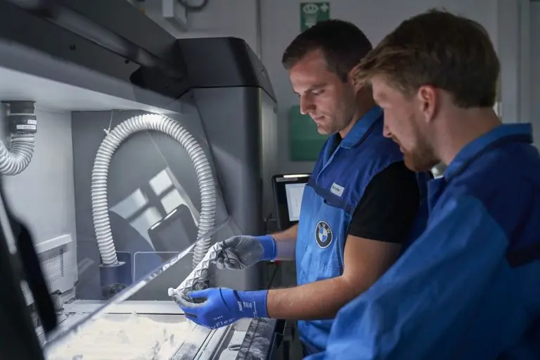
SLS printers are complex, and regular maintenance is crucial. Clean the build chamber after each use, inspect the laser for alignment issues, and replace worn-out components (e.g., recoater blades) as needed.
4. Streamlining Post-Processing
4.1 Simplify Depowdering
Use compressed air, brushes, or dedicated depowdering stations to efficiently remove unsintered powder. For large-scale production, invest in automated depowdering machines.
4.2 Improve Surface Finish
SLS parts often have a grainy texture. Finishing methods like bead blasting, chemical smoothing, or sanding can improve the surface finish. Combining techniques may yield better results.
4.3 Add Coloring or Coatings
Use dyeing systems designed for SLS materials for even coloring. For functional coatings, consider options like polyurethane or epoxy to enhance durability.
5. Reducing Costs Without Sacrificing Quality
5.1 Maximize Powder Usage
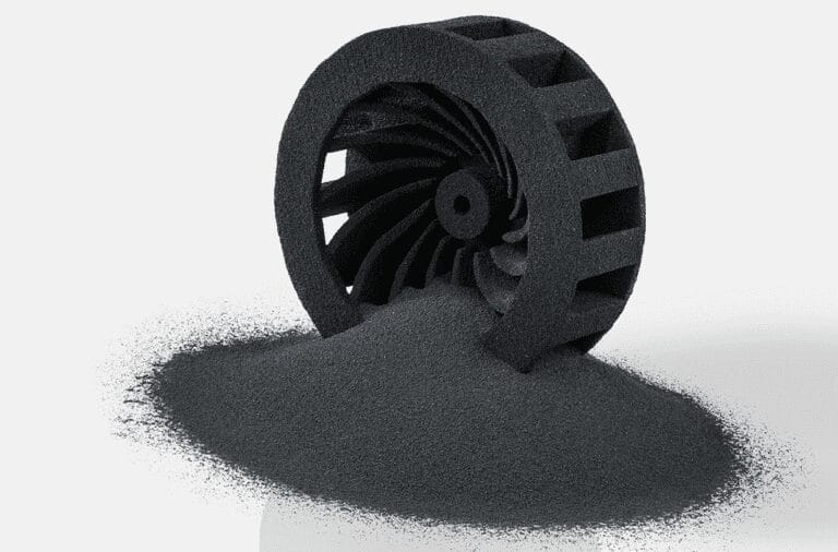
Develop a consistent powder recycling strategy and track powder usage to minimize waste and control material costs.
5.2 Optimize Build Volume
Stack or nest parts to maximize the number of components printed in a single build. Utilize part-packing algorithms in slicing software to optimize space utilization.
5.3 Outsource When Necessary
If printing frequency is low, outsourcing SLS jobs to a service provider may be more cost-effective than maintaining an in-house machine. Compare the outsourcing cost to the total cost of printer ownership (including maintenance and materials).
Advanced Troubleshooting for SLS 3D Printing
1. Identifying Common SLS Printing Defects
1.1 Dimensional Inaccuracies
Parts may not meet design tolerances, being too large or small. Causes can include material shrinkage during cooling, improper scaling in the design or slicing stage, or uneven heat distribution in the build chamber.
1.2 Weak Mechanical Properties
Brittle parts or those lacking strength may be due to insufficient laser power, improper scanning speed, poor powder quality or degradation, or inadequate sintering of layers.
1.3 Surface Imperfections
Rough textures, visible lines, or irregular surfaces can result from uneven sintering of powder, incorrect layer thickness, recoater issues, or suboptimal post-processing techniques.
1.4 Warping or Curling
Parts may deform during printing or after cooling. This can be caused by thermal stress from uneven cooling, non-uniform wall thickness in the part design, or insufficient support from surrounding powder.
1.5 Porosity and Inconsistent Density
Internal voids or inconsistent density, leading to weak areas, can be caused by insufficient laser energy to fully melt the powder or poor layer bonding due to incorrect process settings.
2. Performing Root Cause Analysis
2.1 Check Material Quality
Inspect the powder for signs of degradation (e.g., clumping or discoloration), measure particle size distribution, and analyze the ratio of virgin to recycled powder. Tools like particle analyzers, material data sheets, and storage logs can be used.
2.2 Review Printer Settings
Verify laser power, scanning speed, and energy density settings. Check for consistent layer thickness and powder spreading. Ensure the build chamber maintains a uniform temperature. Printer logs, manufacturer calibration guidelines, and thermal cameras can assist.
2.3 Inspect Part Design
Examine CAD models for thin walls, sharp edges, or unsupported overhangs. Simulate the print in slicing software to identify potential stress points. Validate design tolerances and scaling. CAD software, simulation tools, and design guidelines are useful.
2.4 Evaluate the Printing Environment
Monitor the build chamber for temperature fluctuations, check for environmental factors like humidity or dust contamination, and inspect the recoater blade for damage or uneven spreading. Environmental sensors, recoater inspection tools, and printer maintenance logs can help.
3. Implementing Solutions for Persistent Problems
3.1 Solving Dimensional Inaccuracies
Adjust scaling factors in slicing software to compensate for material shrinkage. Use temperature-controlled cooling cycles to minimize thermal stress. Ensure proper printer calibration, especially for laser alignment and layer thickness.
3.2 Improving Mechanical Properties
Increase laser power or reduce scanning speed to ensure complete sintering. Use fresh or properly recycled powder to improve layer bonding. Check for proper powder bed density by ensuring even powder distribution.
3.3 Enhancing Surface Finish
Adjust layer thickness settings for finer detail. Inspect the recoater blade and replace if necessary. Post-process parts using bead blasting, sanding, or chemical smoothing.
3.4 Minimizing Warping or Curling
Modify the design to include uniform wall thickness and fillets at sharp corners. Ensure the build chamber temperature is consistent to reduce thermal gradients. Use nesting and part orientation strategies to reduce thermal stress.
3.5 Reducing Porosity
Optimize laser energy density for the material. Decrease layer height to improve layer bonding. Perform test prints to determine the ideal balance of process parameters.
4. Proactive Maintenance to Prevent Future Issues
4.1 Routine Machine Maintenance
Clean the build chamber and recoater after each print job. Check laser alignment and calibrate periodically. Replace consumables like filters and recoater blades as needed.
4.2 Monitoring Powder Usage
Track the number of uses for each batch of powder. Maintain detailed logs of powder recycling ratios and performance. Regularly test powder for flowability and particle size.
4.3 Documenting Process Parameters
Record successful print parameters for future reference. Create troubleshooting guides for common defects. Use process monitoring tools to gather real-time data during printing.
5. Advanced Tools and Techniques for Troubleshooting
5.1 Simulation Software
Tools like Materialise Magics or Autodesk Netfabb can simulate print jobs, predict defects, and optimize part orientation.
5.2 Thermal Imaging
Employ thermal cameras to monitor heat distribution in the build chamber.
5.3 In-Process Monitoring
Invest in printers with real-time process monitoring capabilities to detect errors as they occur.
5.4 Powder Analysis Tools
Use particle size analyzers and flowability testers to ensure consistent material quality.
Industry Insights and Innovations in SLS 3D Printing
1. Emerging Trends and Innovations in SLS Technology
1.1 Multi-Laser SLS Systems
Traditional SLS systems rely on a single laser, limiting print speeds. Multi-laser systems, like EOS’s EOS P 500 with dual lasers, increase build speeds and reduce production times, making them suitable for large-scale industrial applications.
1.2 Advancements in Materials
New materials such as carbon-fiber-reinforced nylons, elastomeric powders (TPU), and metal-polymer composites expand the applications of SLS in various industries.
1.3 Automation in Post-Processing
Automated depowdering systems and robotic finishing tools, like AMT PostProDP and Dyemansion’s Powershot systems, reduce labor costs and streamline workflows, enhancing the scalability of SLS for mass production.
1.4 AI and Machine Learning in SLS Optimization
AI is applied in predicting print failures, optimizing part orientation and nesting, and enhancing powder recycling efficiency, improving part quality and reducing production cycles.
2. Real-World Applications and Case Studies
2.1 Aerospace Industry
Aerospace requires lightweight, durable parts with complex geometries. SLS enables the production of such components, like GE Aviation’s ducting and fuel nozzles, reducing weight and integrating multiple parts.
2.2 Automotive Industry
SLS is used for rapid prototyping and low-volume production in the automotive sector. BMW uses it to create custom jigs and fixtures, improving efficiency and reducing costs.
2.3 Medical Industry
Medical devices need customization and biocompatibility. SLS allows for the production of patient-specific implants, prosthetics, and surgical guides, such as dental aligners and custom prosthetic limbs.
2.4 Consumer Goods
Consumers demand personalized products. SLS enables companies to produce custom eyewear, footwear (e.g., Adidas’ 4D Futurecraft midsole), etc.
3. Challenges That Drive Innovation
3.1 Reducing Costs
SLS printers and materials are expensive. Manufacturers are developing entry-level machines and improving powder recycling methods to address this.
3.2 Expanding Material Diversity
The demand for specialized materials drives research into new formulations.
3.3 Improving Sustainability
High energy usage prompts the adoption of energy-efficient systems and exploration of eco-friendly powders.
4. The Future of SLS 3D Printing
Integration with Traditional Manufacturing
SLS is being integrated with traditional methods like injection molding and CNC machining to create hybrid manufacturing workflows.

